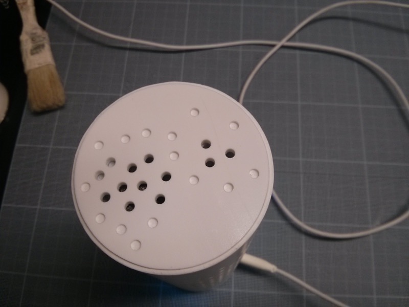
Check hole in top cap to insert pin, correct hole with scalpel if necessary. Add a glue blob on each side of the pin.


Airboxlab – Indoor air quality monitor
This work by Airboxlab S.A. is licensed under CERN OHL v. 1.2.
Index table
This document describes Airboxlab indoor air quality manual step by step. It mandatory to follow the instruction in the described order for a compelling result.
Part names that this document refers to match the ones of the mechanical CAD.
Secondary M2 tap
Small electric screw driver
Pozidrive #1 screw bit
Small Pozidrive #1 screw driver with a rod no lager than 3mm. Alternate: flat 2mm screw driver.
Scalpel with pointed sharp ending blade
Flat elongated pliers (no teeth) to handle connectors
6mm metal drill bit
Pair of cisors
Wire cutters
Glue gun, No silicone based glue (fumes will damaged sensors)
Drill Press
Quantity to assemble one unit.
4x oval head machine screws POZI 2x6mm
4x thermoplastic domed head screws POZI 2.2x8mm
4x countersunk flathead thermoplastic screws POZI 3x10mm
2x Zip-tie 2.5x200mm
4x transparent silicone pads
Electrical tape (~ 25cm)
Transparent office tape (~ 15cm)
Double-sided tape (~ 2cm)
Check hole in top cap to insert pin, correct hole with scalpel if necessary. Add a glue blob on each side of the pin.
Optional if the 2 POZI M2x6 do not hold when using the electrical screw driver: M2 tapping the two holes for the PCB.
Optional if the 2 POZI M2x6 do not hold when using the electrical screw driver: M2 tapping the two holes.
Screw an M2x6 screw from the side with the fins until flush on the flat side:
Countersink 4 holes with drill 6mm metal, plastic film side, of sufficient depth so that POZI 3x10 screw heads are fully embedded:
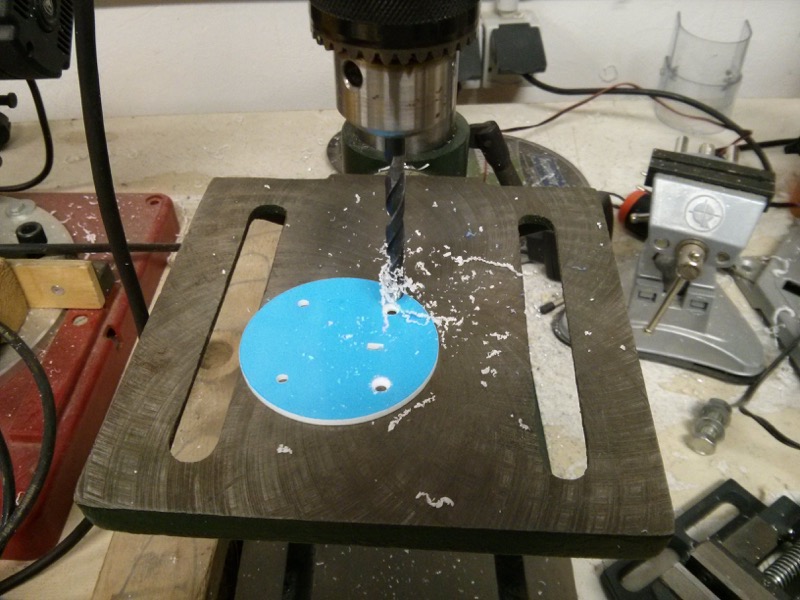
Deburring with scalpel if necessary.
Prepare parts (see 3).
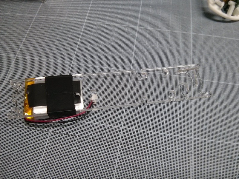
Glue a piece of electrical tape over the battery, on the side where there is nothing written.
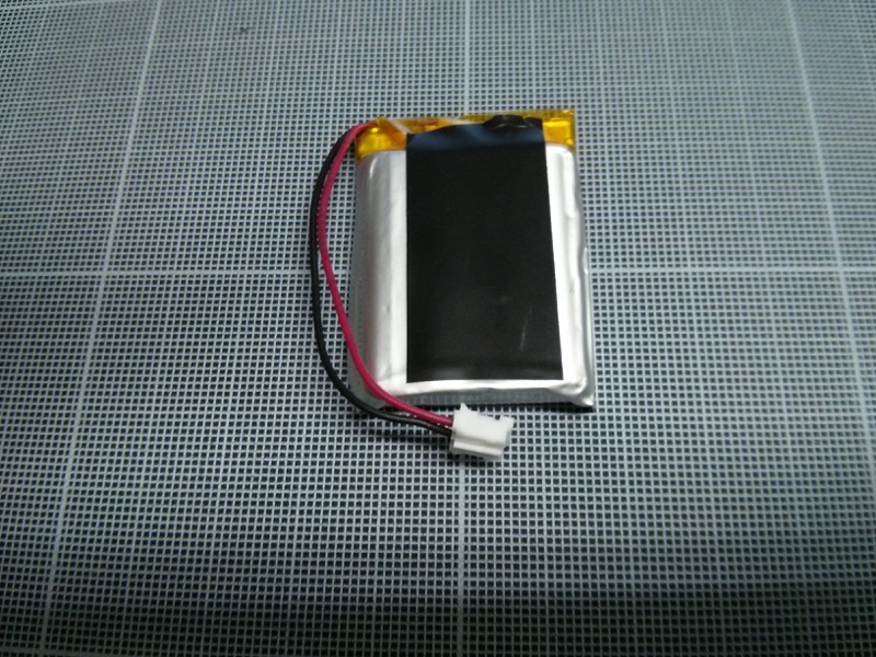
Attach the battery on the side_plate with electrical tape, making sure of the orientation:
Side of the battery with electrical tape is against side_plate.
Battery is about 5mm above the bottom of the side_plate holes.
Battery's wire comes down on the same side that the notches for the wires.
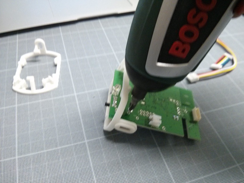
Screw Main_PCB on bottom_part with 2 POZI M2x6 screws
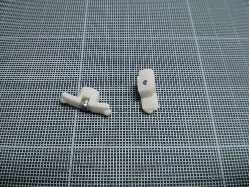
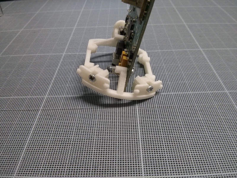
Insert the two pushers in there notches in bottom_part.
Attach the fan and its two supports with two zip-tie (all together this is the top cross_section of airboxlab). Make sure of the orientation of parts: fan airflow direction, fan wire and zip-tie.


Glue GP2Y on middle cross_section. Use a tool to precisely align it, if alignment is wrong it won't enter properly.

Connect GPY2 cable in the sensor then into Main_PCB.

Insert the assembly consisting of Main_PCB + bottom_part in the groove of the bottom cross_section. Check alignment with bottom_part: the sides of bottom_part must be aligned with sides of the cross_section.


Assemble the 3 cross_sections on side_plate to which is attached the battery, starting with the one with the fan.
Place the second side_plate over the whole assembly. Both side_plates must be oriented so as to be superimposed. Check that the fan cable goes well in his small notch at the middle cross_section.

Check that the sections are fully engaged, especially the middle one.
Put a strip of electrical tape (> = 16.5 cm) around the fan and the middle section:

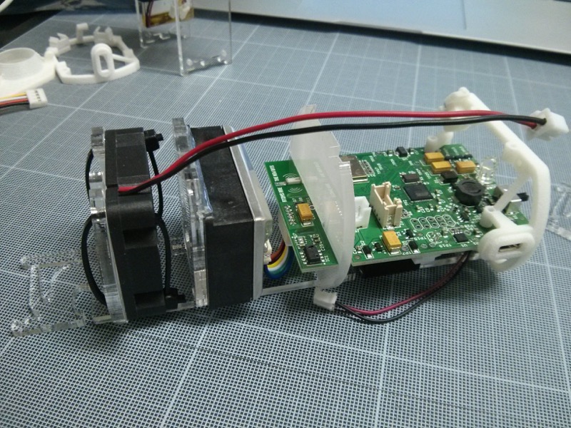
Connect Grove cable on Sensor_PCB.
Clip Sensor_PCB in the side plates and pass Grove cable into its top notch.

Place fan cable then Grove cable into the bottom cable notch.
Connect the fan cable in the Main_PCB using flat pliers.
Plug the cable into the Grove Main_PCB using flat pliers.
Pull excess wire with pliers so that they are snug to the side_plate.
Tape both cables on side_plate (~ 6cm).

Ensure that Main_PCB is totally engaged in the groove of cross_section, so that the edge of the PCB with T/RH sensor is flush along the cross_section.
Screw the side_plates to the bottom_part with 4 thermoplastic POZI 2.2x8mm screws.

Connect the battery.

Insert the whole assembly into the enclosure with LED and USB connector up. Press on the cylinder to modify its roundness so to get the USB into its designated hole.

Place the Roundifiers, cut corners towards the Pushers.

Insert led_pipe disc then the bottom_plate and screw the two together with the 4 3x10mm thermoplastic countersunk screws.

Glue the 4 transparent silicone pads.

Clip the top_cap with pin fitting into the Sensor_PCB's hole to center the inner assembly.

Screw both Pushers until their nipples fit into the holes. The whole assembly should not move, but do not over-tight the screws otherwise the cylinder will misshapen and offset from the lower plates.

Stick two pieces of double-sided tape on the top_cap, remove the protective film and place the top_plate aligning the holes with the sensors. The plate must protrude about 0.5mm from the cylinder.